Building a Scenario Tutorial
This tutorial describes step-by-step instructions for building a scneario using Spacetime’s NBI.
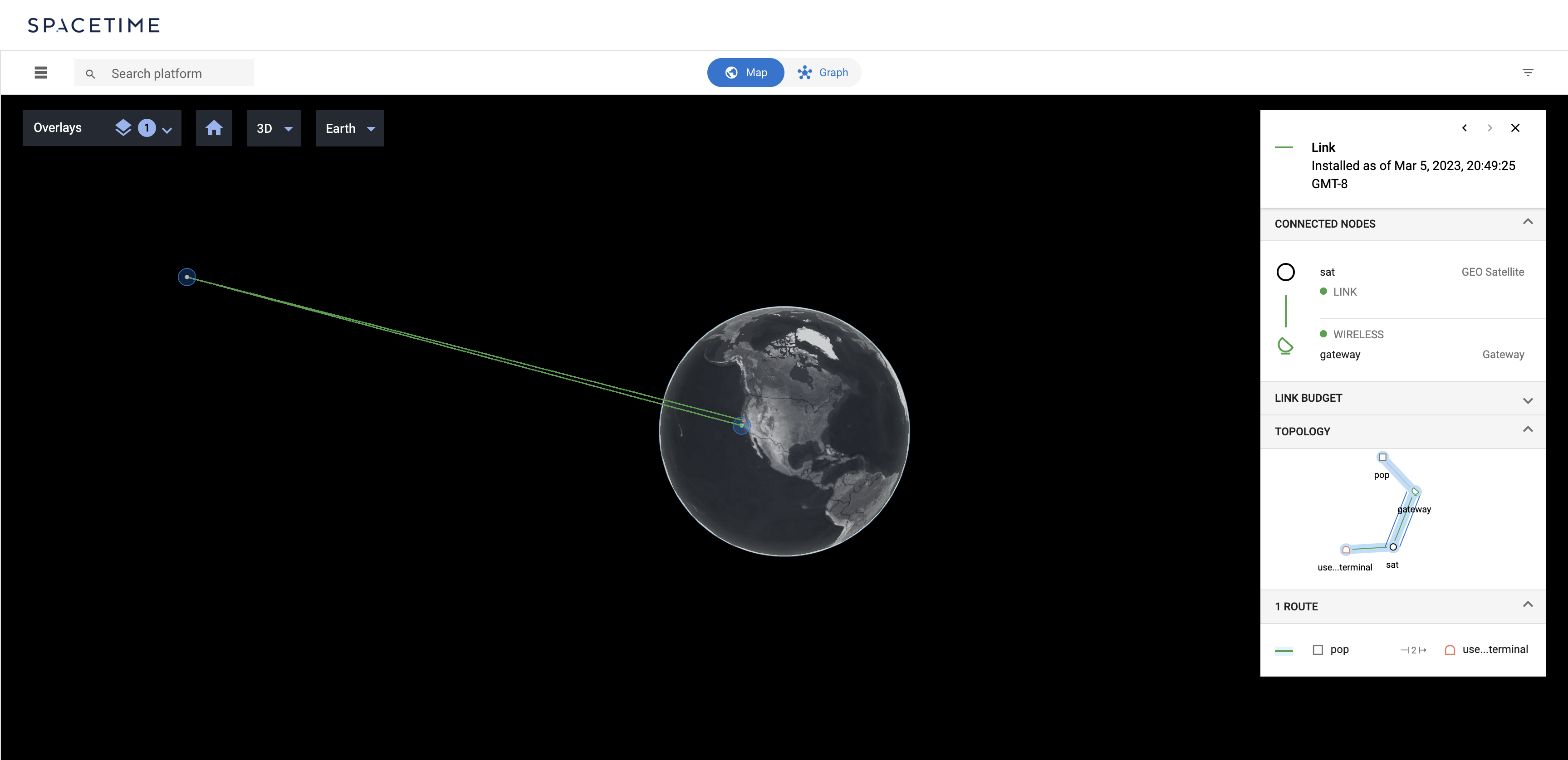
At the end of this tutorial, you will have built a network that looks like this:
gRPC and Protocol Buffers
Calls to Spacetime’s endpoints can be made using the gRPC RPC framework in combination with Protocol Buffers to serialize requests and responses. In practice, this means that software applications that interact with the SDN Controller will call out to these endpoints using client libraries generated by the gRPC framework in your language of choice from our interface descriptions.
ℹ️ For more info detailing the the creation and usage of these client libraries, see the gRPC Basics Tutorial.
However, to get started exploring the APIs without first building an entire application, we can use nbictl, a tool that lets you interact with NBI API from the command-line.
Getting started with nbictl
-
To start accessing the NBI APIs, first generate an Private-Public Keypair using the
nbictl generate-keyscommand:$ nbictl generate-keys --org "my-organization.com" private key is stored under: ~/.config/nbictl/keys/922e75e63659b29b76631275.key certificate is stored under: ~/.config/nbictl/keys/922e75e63659b29b76631275.crtOnce you generated the keypair, you’ll need to send the
.crtfile (a self-signed x509 certificate containing the public key) to Aalyria.⚠️ Only share the public certificate (
.crt) with Aalyria or third-parties. The private key (.key) must be protected and should never be sent by email or communicated to others in any.After granting access to your keypair, Aalyria will provide the
USER_IDandKEY_IDthat identify the keypair within Spacetime. These settings are necessary to configurenbictl, or any SDK Library that allow to authenticate to Spacetime. -
Next step you will have to configure
nbictlwith the right parameters for your Spacetime instance and your keypair.$ nbictl set-config --url "nbi.$INSTANCE.spacetime.aalyria.com:443" $ nbictl set-config --key_id "$KEY_ID" $ nbictl set-config --user_id "$USER_ID" $ nbictl set-config --priv_key "$PRIVATE_KEY_FILE_NAME" -
To verify access to the Spacetime APIs, you can issue a request to
listof all of theNETWORK_NODESpresent in the instance:$ nbictl list --type "NETWORK_NODE"The results returned will depend on the state of the Spacetime instance. It is normal for the results to be empty if no network nodes have yet been created in the instance.
“Entities” and the NBI
Interactions with the NBI happen primarily through the manipulation of
“entities”, which are persistent mutable resources. Each entity has a “type”
that dictates the nature of the data it holds. For example, we queried for
NETWORK_NODE-type entities above. Entity types include ANTENNA_PATTERN
entities, PLATFORM_DEFINITION entities, SERVICE_REQUEST entities, among
others. The complete list of types can be found in our NBI interface
description
here.
By manipulating these entities we can do things such as configure the SDN Controller with the properties of the networks it is orchestrating, or request that traffic be routed across that network.
Entity commit timestamps and optimistic concurrency control
Each version of an entity is automatically assigned a “commit timestamp”. Spacetime assigns a commit timestamp to each entity upon creating it, and that commit timestamp is automatically changed to a new, unique value each time the entity is updated.
Commit timestamps play an important role in Spacetime’s optimistic concurrency control. When updating or deleting an entity one must provide the commit timestamp of the version of the entity being modified. If Spacetime finds that the provided commit timestamp does not match the commit timestamp of the entity being modified, it will reject the change. Such an occurrence indicates that another user has modified the entity concurrently, and the rejection is intended to prevent accidental overwriting of the other user’s changes.
In action
To see this in action, let’s create, update, and then delete a NETWORK_NODE
entity.
-
Create a new
NETWORK_NODEentity using thenbictl createcommandℹ️ The network node created here is functionally useless. It does not have any network interfaces attached. However it will do for now as a means to explore the entity lifecycle.
To create a new entity using
nbictl, we first have to create a.textprotofile that contains entity information you want to create.entity { group { type: NETWORK_NODE } network_node { name: "my-node" } }After creating the
.textprotofile, let’s create a new network node entity by running:$ nbictl create --files="~/path/to/*.textproto"Spacetime will respond with the created entity. It should look something like:
entity {
  group {
    type: NETWORK_NODE
  }
  id: "8fbff64e-d12a-47b2-9a85-117492ac4aad"
  commit_timestamp: 1690841566394521
  network_node {
    name: "my-node"
  }
}
Note that Spacetime has assigned the entity an ID and a commit timestamp.
-
Now, let’s modify the network node entity by invoking the
nbictl updatecommand. We’ll attach a network interface to the network node entity. Recall that, for concurrency control, we must provide the commit timestamp of the entity version we are overwriting.First, similar to when creating a new entity, let’s create a
.textprotofile that contains an updates for an entity:entity { commit_timestamp: 1690841566394521 id: "8fbff64e-d12a-47b2-9a85-117492ac4aad" group { type: NETWORK_NODE } network_node { name: "my-node" node_interface { interface_id: "eth0" wired {} } } }Then, run:
$ nbictl update --files="~/path/to/*.textproto"Spacetime should then respond with the updated entity, something like:
 entity {
   group {
     type: NETWORK_NODE
   }
   id: "8fbff64e-d12a-47b2-9a85-117492ac4aad"
   commit_timestamp: 1690841671414501
   network_node {
     name: "my-node"
     node_interface {
         interface_id: "eth0"
         wired {}
     }
   }
 }
Note that Spacetime has changed the entity’s commit timestamp to reflect the new revision of the entity.
-
Finally, we can delete the network node entity by invoking the
nbictl deletecommand. Once more, we must include the commit timestamp of the entity we are modifying:$ nbictl delete \ --id "8fbff64e-d12a-47b2-9a85-117492ac4aad" \ --last_commit_timestamp 1690841671414501 --type "NETWORK_NODE"
Defining a network
The entity types essential for defining a network are:
-
PLATFORM_DEFINITIONentities, which define instances of physical objects (“platforms”) in the network (satellites, ships, or aircraft, for instance). The entities specify attributes of the platforms, including their motion, and any wireless transceivers mounted on the platforms. -
ANTENNA_PATTERNentities, which define any three-dimensional antenna radiation patterns needed to describe the radiation or receiving properties of any antennas in the network. -
BAND_PROFILEentities, which define the wireless frequency bands with which the network’s transceivers are compatible. -
NETWORK_NODEentities, which define the logical network devices in the network and their attributes, including IP addresses and subnets. -
INTERFACE_LINK_REPORTentities, which define the static links in the network. Most typically these are used to define a terrestrial network topology.
We can employ the CreateEntity, UpdateEntity, and DeleteEntity operations
on entities of these types to define networks in Spacetime. As an example,
let’s define a simple network composed of a satellite, a user terminal, a
gateway, and a
point of presence (PoP).
The user terminal and gateway will each have a single transmitter and receiver. The satellite will have two: one for the user link and one for the gateway link.
Defining a band profile
First we’ll create a BAND_PROFILE representing a wireless band made up of
250 MHz-wide channels. This will define the wireless medium to be used by the
wireless links in our network. In the same entity we must also define a “rate
table” specifying how the capacity of a link in this band depends on the
SNIR
at a receiver.
bandprofile.textproto file:
entity {
  id: "test-band-profile"
  group {
    type: BAND_PROFILE
  }
  band_profile {
    channel_width_hz: 250000000
    rate_table {
      received_signal_power_steps {
        min_received_signal_power_dbw: -100
        tx_data_rate_bps: 1e8
      }
      received_signal_power_steps {
        min_received_signal_power_dbw: -90
        tx_data_rate_bps: 2e8
      }
      received_signal_power_steps {
        min_received_signal_power_dbw: -80
        tx_data_rate_bps: 3e8
      }
    }
  }
}
$ nbictl create --files="~/path/to/band_profile.textproto
Defining antenna patterns
Next, we can use antenna patterns to define how radiation is emitted or received from the antennas in the network. For now, we’ll assume that all antennas in our network are identical, so a single antenna pattern is sufficient:
ℹ️ In the interest of simplicity, we’ll assume our antennas are all parabolic, though Spacetime supports arbitrary user-defined radiation patterns.
antenna_pattern.textprotofile:
entity {
  id: "test-antenna-pattern"
  group {
    type: ANTENNA_PATTERN
  }
  antenna_pattern {
    parabolic_pattern {
      diameter_m: 1
      efficiency_percent: 0.9
      backlobe_gain_db: -60
    }
  }
}
$ nbictl create --files="~/path/to/antenna_pattern.textproto"
Defining the user terminal
We can now begin defining the network assets themselves. The user terminal,
gateway, and satellite will each be defined by a combination of two entities:
(1) PLATFORM_DEFINITION entity defining the physical characteristics of the
asset and (2) a NETWORK_NODE entity defining the logical network attributes
of the asset.
To define the user terminal, we first create its PLATFORM_DEFINITION
entity. In a 5G non-terrestrial networking (NTN) architecture, this would
correspond to user equipment.
user_terminal.textproto file:
entity {
  id: "test-user-terminal-platform-definition"
  group {
    type: PLATFORM_DEFINITION
  }
  platform {
    name: "user-terminal"
    type: "UserTerminal"
    coordinates {
      geodetic_wgs84 {
        longitude_deg: -121.7
        latitude_deg: 37.7
      }
    }

    transceiver_model {
      id: "transceiver-model"

      transmitter {
        name: "tx"
        channel_set {
          key: "test-band-profile"
          value {
            channel {
              key: 1000000000
              value {
                max_power_watts: 100
              }
            }
          }
        }
        signal_processing_step {
          amplifier {
            constant_gain {
              gain_db: 10
              noise_factor: 1
              reference_temperature_k: 290
            }
          }
        }
      }

      receiver {
        name: "rx"
        channel_set {
          key: "test-band-profile"
          value {
            center_frequency_hz: 12000000000
          }
        }
        signal_processing_step {
          amplifier {
            constant_gain {
              gain_db: 10
              noise_factor: 1
              reference_temperature_k: 290
            }
          }
        }
      }

      antenna {
        name: "antenna"
        antenna_pattern_id: "test-antenna-pattern"
        targeting {}
      }

      macs {
        type: "DVBS2"
        role: "HUB"
        max_connections: 1
      }
    }
  }
}
$ nbictl create --files="~/path/to/user_terminal.textproto"
This entity is verbose, but it is fairly simple. In short, it specifies that:
- The user terminal is placed on the ground in Livermore, California.
- The user terminal has a single transceiver, operating in the band we defined
earlier (note the
test-band-profilereference). - The transmitter is capable of operating at 11 Ghz, while the receiver operates at 12 GHz.
- The transmit and receive signal chains each contain a low-noise amplifier.
- The attached antenna exihibits the radiation properties of a 1 meter
parabolic dish as defined earlier (note the
test-antenna-patternreference). - The attached antenna is steerable.
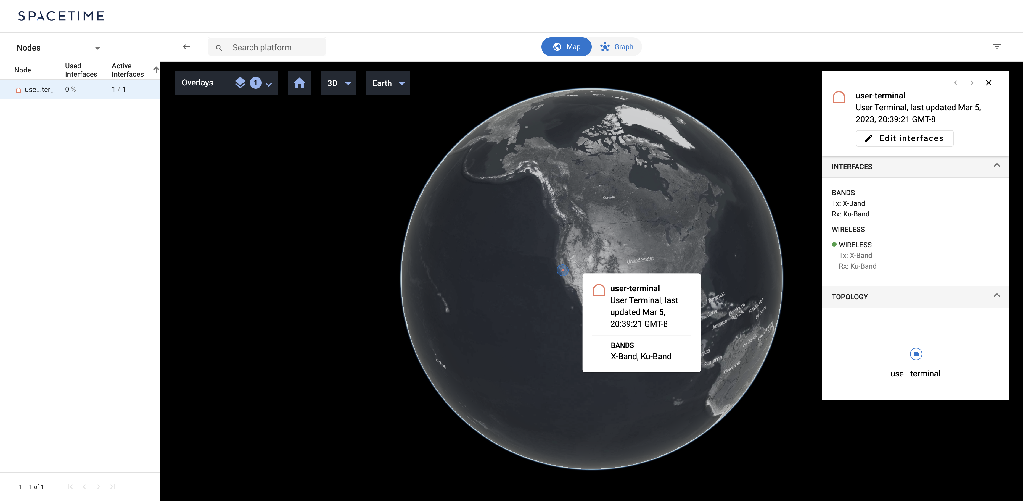
The Map tab of your scenario should now resemble:
Now we define the user terminal’s NETWORK_NODE to represent its logical
network representation.
user_terminal_network_node.textproto file:
entity {
  id: "test-user-terminal-network-node"
  group {
    type: NETWORK_NODE
  }
  network_node {
    name: "user-terminal"
    type: "UserTerminal"
    subnet: "107.89.175.219/32"
    node_interface {
      interface_id: "wireless"
      wireless {
        transceiver_model_id {
          platform_id: "test-user-terminal-platform-definition"
          transceiver_model_id: "transceiver-model"
        }
      }
    }
    subnet: "fd00:0:0:2a:0:0:0:0/64"
  }
}
$ nbictl create --files="~/path/to/user_terminal_network_node.textproto"
This entity declares a network node with a single interface, and ties the interface to the user terminal’s transceiver. This means that the interface’s connectivity is determined by the connectivity of the transceiver.
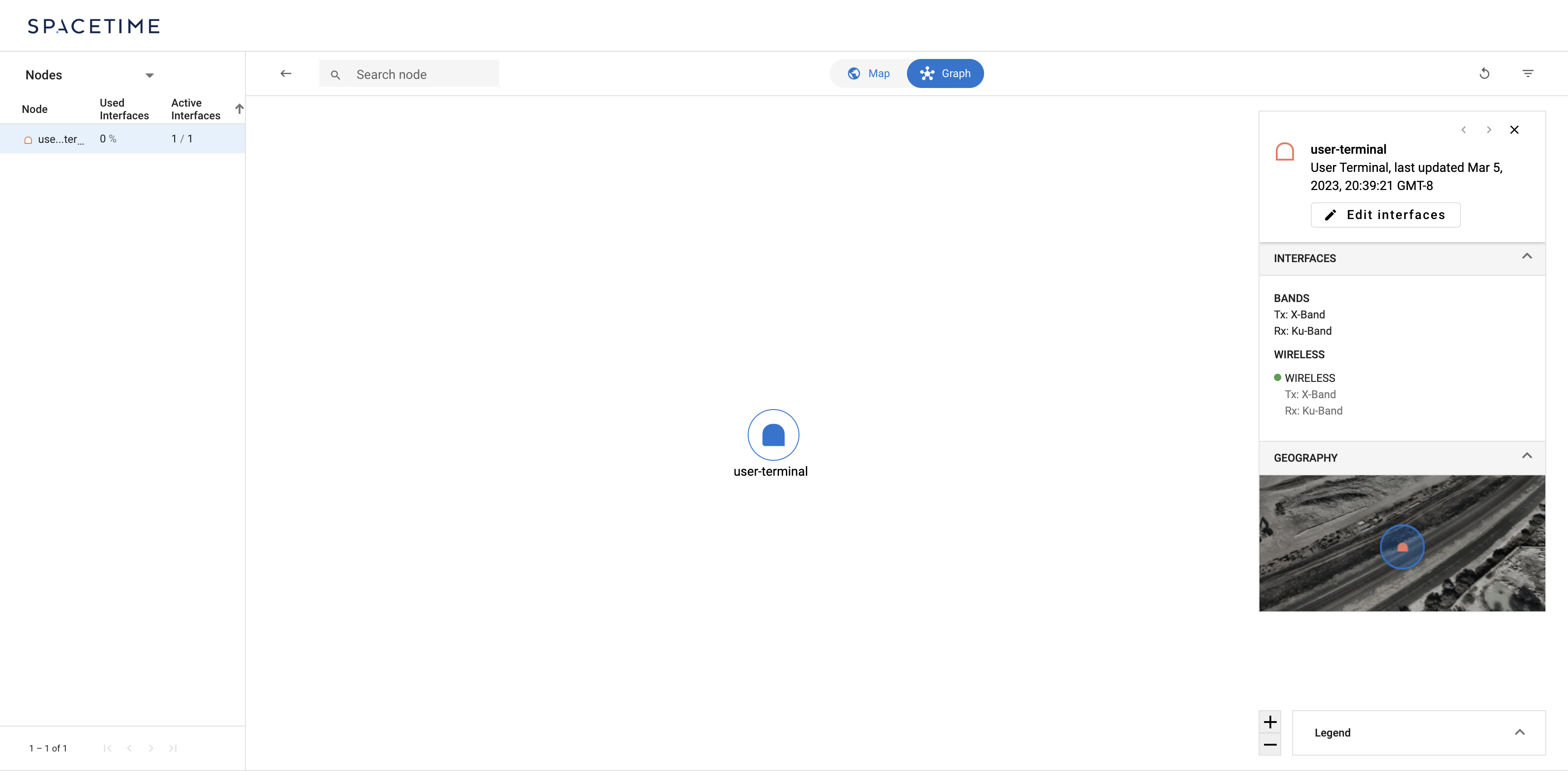
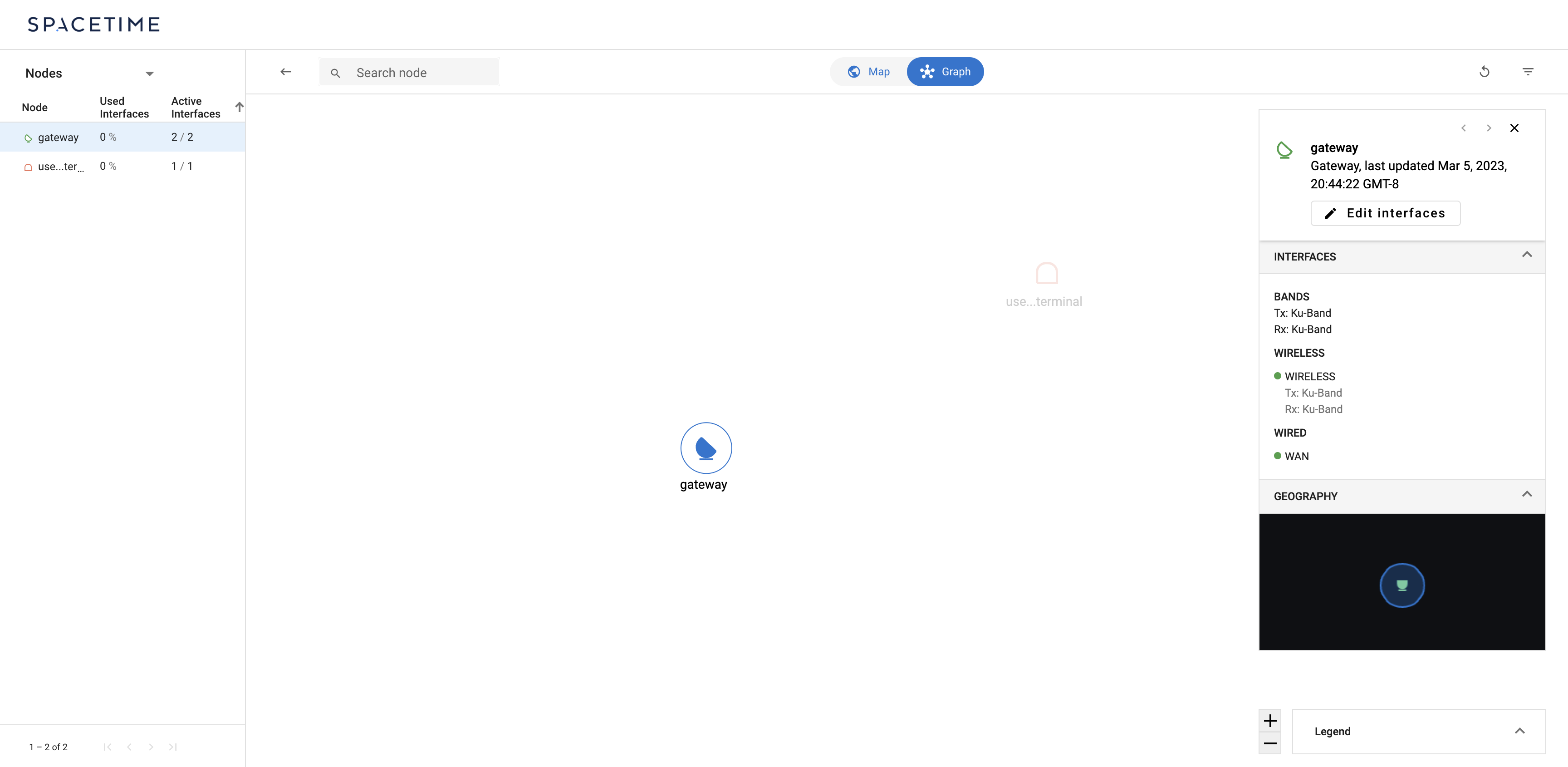
The Graph tab of your scenario should now resemble:
And with that, our user terminal is complete. We’ll follow a similar process for the remaining assets.
Defining the gateway
The gateway is much like the user terminal except that:
- Its location is different.
- In addition to its wireless interface, it also has a WAN-facing wired interface attached.
In a 5G non-terrestrial networking (NTN) architecture, this would
correspond to a gNodeB (or basestation).
gateway.textproto file:
entity {
  id: "test-gateway-platform-definition"
  group {
    type: PLATFORM_DEFINITION
  }
  platform {
    name: "gateway"
    type: "Gateway"
    coordinates {
      geodetic_wgs84 {
        longitude_deg: -121.1
        latitude_deg: 35.4
      }
    }

    transceiver_model {
      id: "transceiver-model"

      transmitter {
        name: "tx"
        channel_set {
          key: "test-band-profile"
          value {
            channel {
              key: 13000000000
              value {
                max_power_watts: 100
              }
            }
          }
        }
        signal_processing_step {
          amplifier {
            constant_gain {
              gain_db: 10
              noise_factor: 1
              reference_temperature_k: 290
            }
          }
        }
      }

      receiver {
        name: "rx"
        channel_set {
          key: "test-band-profile"
          value {
            center_frequency_hz: 14000000000
          }
        }
        signal_processing_step {
          amplifier {
            constant_gain {
              gain_db: 10
              noise_factor: 1
              reference_temperature_k: 290
            }
          }
        }
      }

      antenna {
        name: "antenna"
        antenna_pattern_id: "test-antenna-pattern"
        targeting {}
      }

      macs {
        type: "DVBS2"
        role: "HUB"
        max_connections: 1
      }
    }
  }
}
$ nbictl create --files="~/path/to/gateway.textproto"
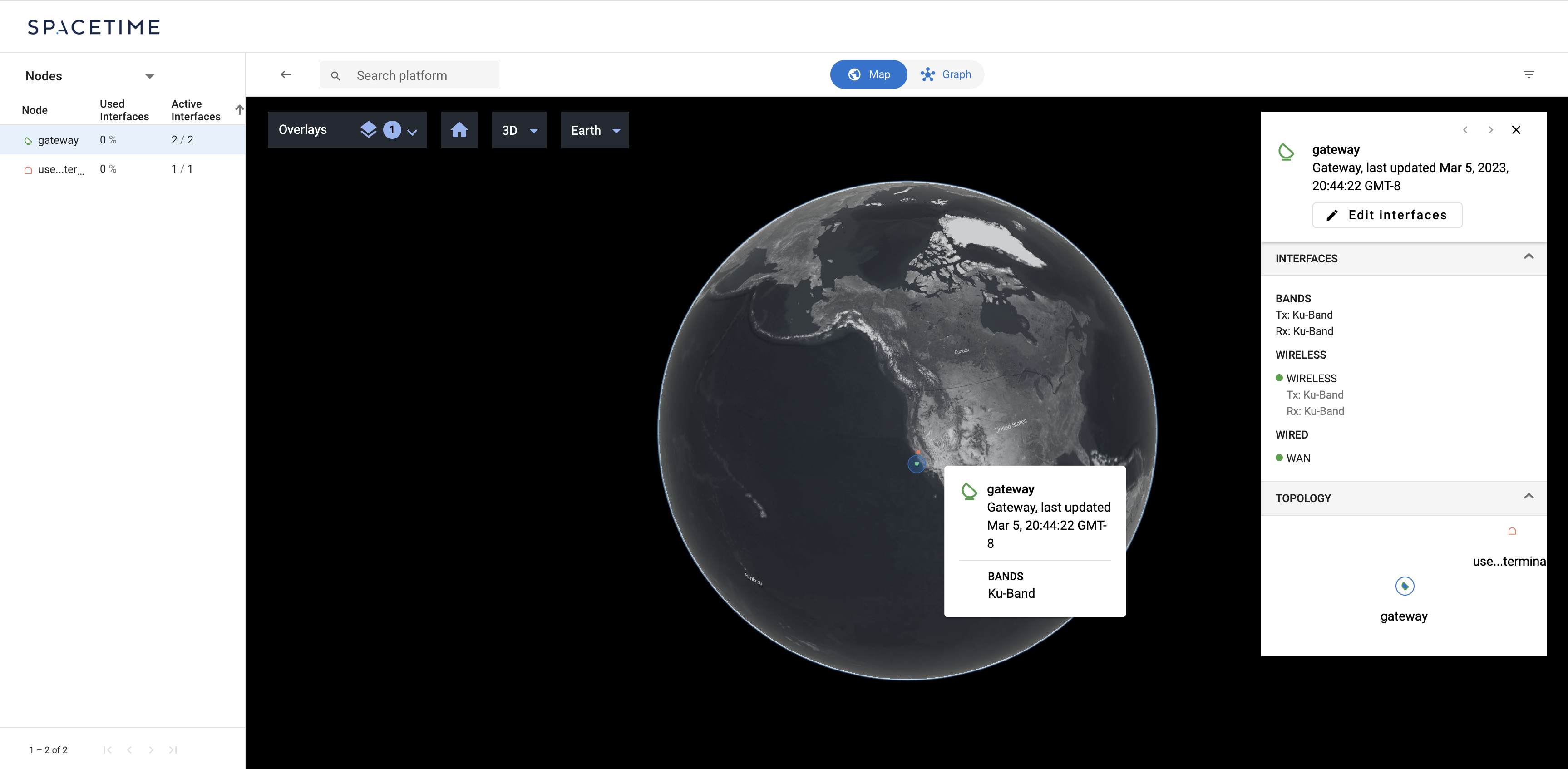
The Map tab of your scenario should now resemble:
gateway_network_node.textproto file:
entity {
  id: "test-gateway-network-node"
  group {
    type: NETWORK_NODE
  }
  network_node {
    name: "gateway"
    type: "Gateway"
    subnet: "211.154.172.215/32"
    node_interface {
      interface_id: "wireless"
      wireless {
        transceiver_model_id {
          platform_id: "test-gateway-platform-definition"
          transceiver_model_id: "transceiver-model"
        }
      }
    }
    node_interface {
      interface_id: "wan"
      wired {}
    }
  }
}
$ nbictl create --files="~/path/to/gateway_network_node.textproto"
The Graph tab of your scenario should now resemble:
Defining the satellite
The configuration required to define a satellite is not dramatically different from that required to define a user terminal or gateway. Among them the satellite is unique however in that:
- It has two transceivers: one for the user link and one for the gateway link.
- It is in GEO.
For the sake of this tutorial, we will assume that our satellite has a fixed position, but Spacetime supports defining many complex types of motion.
In a 5G NTN architecture, these satellites might use FR1 or FR2 bands.
satellite.textproto file:
entity {
  id: "test-satellite-platform-definition"
  group {
    type: PLATFORM_DEFINITION
  }
  platform {
    name: "sat"
    type: "GEO"
    coordinates {
      geodetic_wgs84 {
        longitude_deg: -121.1
        latitude_deg: 37.4
        height_wgs84_m: 36000000
      }
    }

    transceiver_model {
      id: "user-link-transceiver-model"

      transmitter {
        name: "tx"
        channel_set {
          key: "test-band-profile"
          value {
            channel {
              key: 12000000000
              value {
                max_power_watts: 100
              }
            }
          }
        }
        signal_processing_step {
          amplifier {
            constant_gain {
              gain_db: 10
              noise_factor: 1
              reference_temperature_k: 290
            }
          }
        }
      }

      receiver {
        name: "rx"
        channel_set {
          key: "test-band-profile"
          value {
            center_frequency_hz: 11000000000
          }
        }
        signal_processing_step {
          amplifier {
            constant_gain {
              gain_db: 10
              noise_factor: 1
              reference_temperature_k: 290
            }
          }
        }
      }

      antenna {
        name: "antenna"
        antenna_pattern_id: "test-antenna-pattern"
        targeting {}
      }

      macs {
        type: "DVBS2"
        role: "REMOTE"
        max_connections: 1
      }
    }

    transceiver_model {
      id: "gateway-link-transceiver-model"

      transmitter {
        name: "tx"
        channel_set {
          key: "test-band-profile"
          value {
            channel {
              key: 14000000000
              value {
                max_power_watts: 100
              }
            }
          }
        }
        signal_processing_step {
          amplifier {
            constant_gain {
              gain_db: 10
              noise_factor: 1
              reference_temperature_k: 290
            }
          }
        }
      }

      receiver {
        name: "rx"
        channel_set {
          key: "test-band-profile"
          value {
            center_frequency_hz: 13000000000
          }
        }
        signal_processing_step {
          amplifier {
            constant_gain {
              gain_db: 10
              noise_factor: 1
              reference_temperature_k: 290
            }
          }
        }
      }

      antenna {
        name: "antenna"
        antenna_pattern_id: "test-antenna-pattern"
        targeting {}
      }

      macs {
        type: "DVBS2"
        role: "REMOTE"
        max_connections: 1
      }
    }
  }
}
$ nbictl create --files="~/path/to/satellite.textproto"
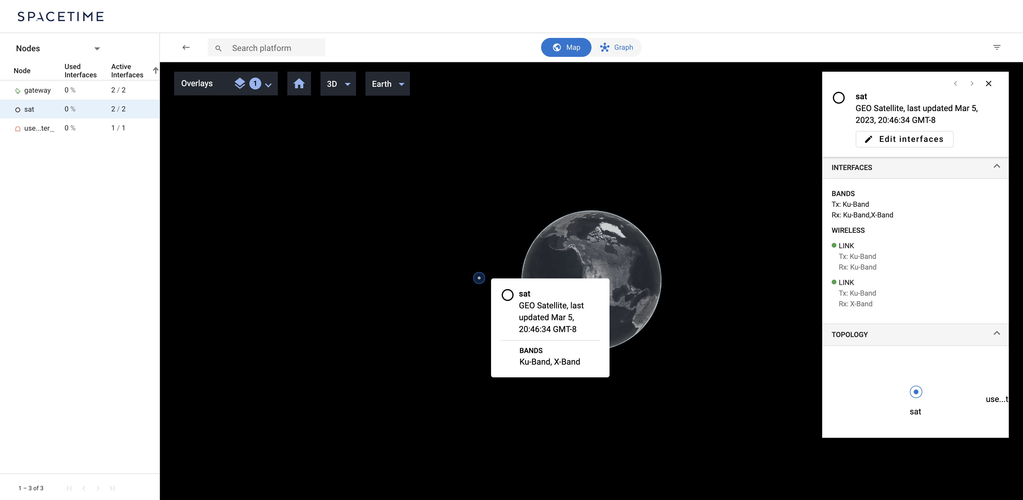
The Map tab of your scenario should now resemble:
satellite_network_node.textproto file:
entity {
  id: "test-satellite-network-node"
  group {
    type: NETWORK_NODE
  }
  network_node {
    name: "sat"
    type: "GEO"
    subnet: "191.165.104.62/32"
    node_interface {
      interface_id: "user-link"
      wireless {
        transceiver_model_id {
          platform_id: "test-satellite-platform-definition"
          transceiver_model_id: "user-link-transceiver-model"
        }
      }
    }
    node_interface {
      interface_id: "gateway-link"
      wireless {
        transceiver_model_id {
          platform_id: "test-satellite-platform-definition"
          transceiver_model_id: "gateway-link-transceiver-model"
        }
      }
    }
  }
}
$ nbictl create --files="~/path/to/satellite_network_node.textproto"
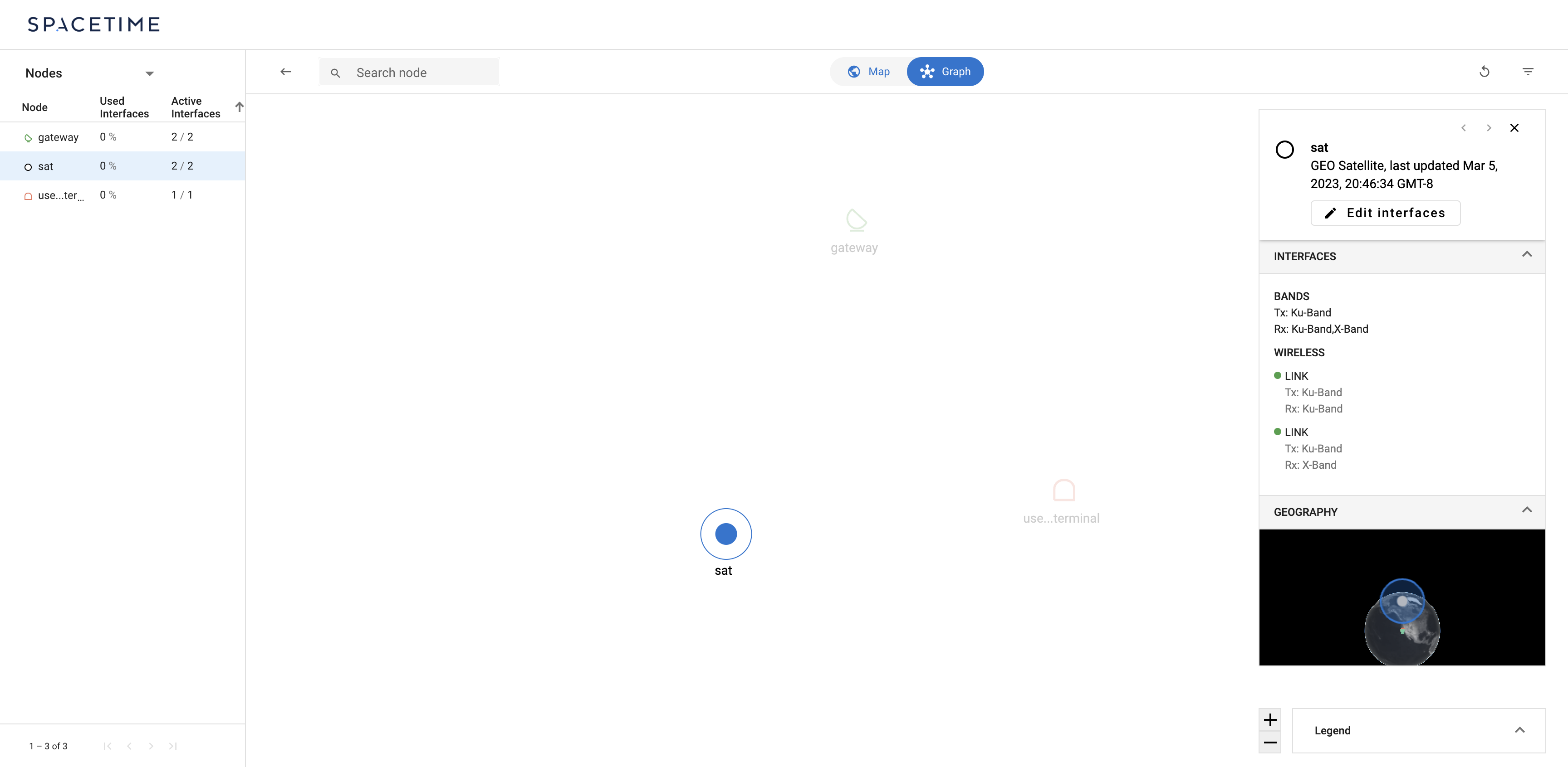
Your scenario should now resemble:
Defining the terrestrial network
Finally, let’s define the terrestrial network. The network is to be made up of
a point of presence (PoP) connected to the gateway by a terrestrial link. It is
worth noting that while the user terminal, gateway, and satellite were all
defined using a combination of a PLATFORM_DEFINITION entities and
NETWORK_NODE entities, the PoP can be defined without a PLATFORM_DEFINITON
at all. This is because the PoP has no wireless interfaces, so connectivity to
the PoP is not impacted by the physical attributes one might specify in a
PLATFORM_DEFINITION.
We begin with the PoP’s NETWORK_NODE:
pop_network_node.textproto file:
entity {
  id: "test-pop-network-node"
  group {
    type: NETWORK_NODE
  }
  network_node {
    name: "pop"
    type: "POP"
    subnet: "121.201.204.104/32"
    node_interface {
      interface_id: "wan"
      wired {}
    }
  }
}
$ nbictl create --files="~/path/to/terrestrial_network_node.textproto"
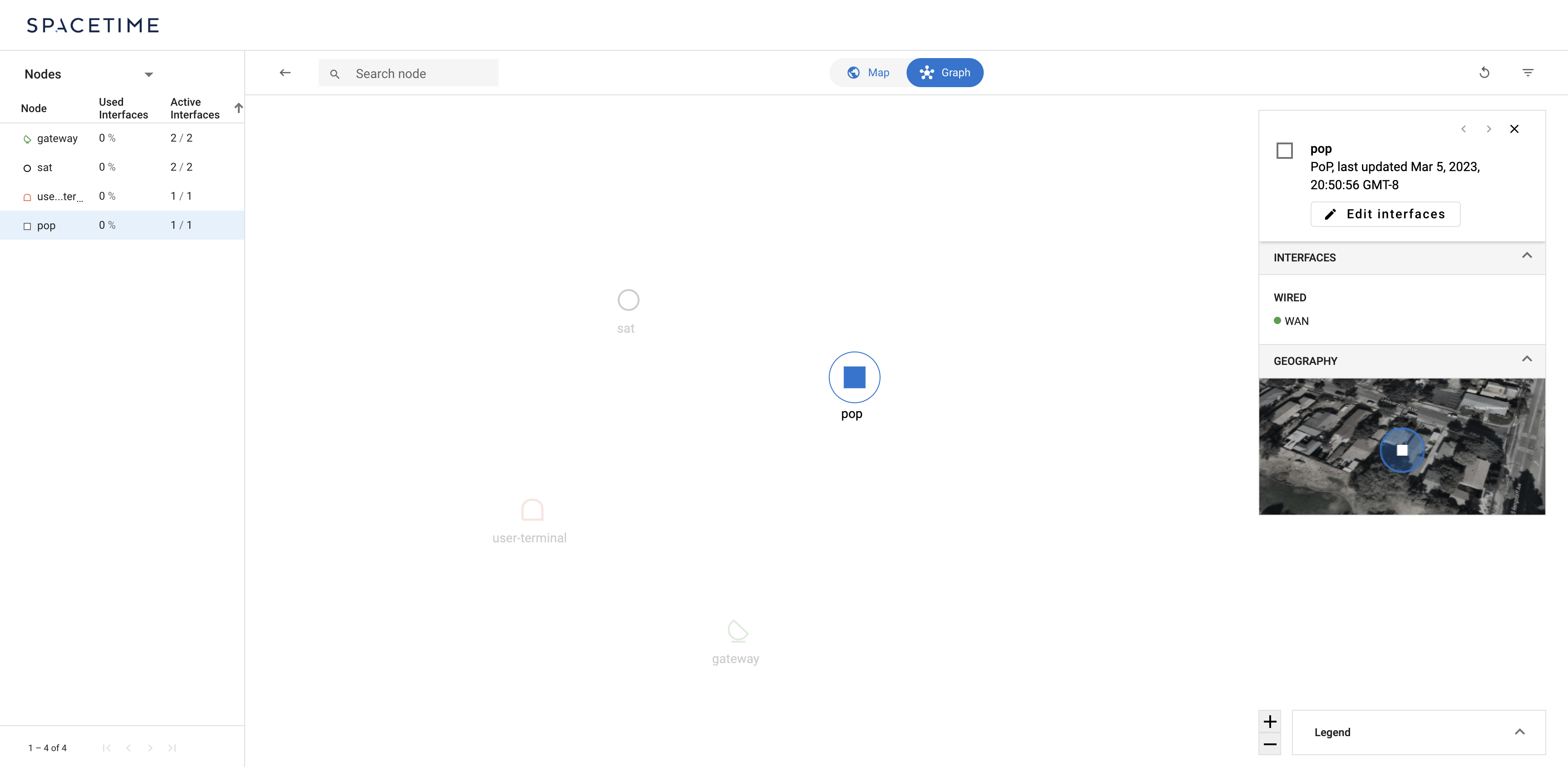
The Graph tab of your scenario should now resemble:
And then we can add the terrestrial links. One from the PoP to the gateway:
terrestrial_gateway.textproto file:
entity {
  id: "test-pop-to-gateway-interface-link-report"
  group {
    type: INTERFACE_LINK_REPORT
  }
  interface_link_report {
    src {
      node_id: "test-pop-network-node"
      interface_id: "wan"
    }
    dst {
      node_id: "test-gateway-network-node"
      interface_id: "wan"
    }
    access_intervals {
      accessibility: ACCESS_EXISTS
      data_rate_bps: 1e+12
    }
  }
}
$ nbictl create --files="~/path/to/terrestrial_gateway.textproto"
and then another in the opposite direction:
terrestrial_gateway_opposite.textproto file:
entity {
  id: "test-gateway-to-pop-interface-link-report"
  group {
    type: INTERFACE_LINK_REPORT
  }
  interface_link_report {
    src {
      node_id: "test-gateway-network-node"
      interface_id: "wan"
    }
    dst {
      node_id: "test-pop-network-node"
      interface_id: "wan"
    }
    access_intervals {
      accessibility: ACCESS_EXISTS
      data_rate_bps: 1e+12
    }
  }
}
$ nbictl create --files="terrestrial_gateway_opposite.textproto"
and with that, we’ve completed our definition of a minimal network.
Requesting a service
Spacetime orchestrates a network with the objective of satisfying or fulfilling
services requested of the network. So, to see Spacetime’s orchestration in
action, we must issue a service request. This can be accomplished by creating a
SERVICE_REQUEST entity. Let’s request service between the user terminal and
the PoP:
service_request.textproto file:
entity {
  id: "test-pop-to-user-terminal-service-request"
  group {
    type: SERVICE_REQUEST
  }
  service_request {
    src_node_id: "test-pop-network-node"
    dst_node_id: "test-user-terminal-network-node"
    requirements {
      bandwidth_bps_requested: 1e+06
    }
  }
}
$ nbictl create --files="~/path/to/service_request.textproto
The Map tab of your scenario should now resemble:
And that’s it! Head to the Github repository to understand the range of Spacetime’s object model and how to express more complex network capabilities.